- 5. Software
-
- 5.1 Development environment
- 5.2 Main program
- 5.3 DSP/BIOS configuration
- 5.4 Librairies
- 5.5 Include files
- 5.6 GEL files
- 5.7 Real-time implementation
- 5.7.1 Scheduling
- 5.7.2 Analysis
- 5.7.3 Processing
- 5.7.4 Synthesis
- 5.7.5 Resampling
5. Software
We have the algorithm and the hardware: we are now ready to write the software.
5.1 Development environment
The software is designed with Code Composer Studio (v3.3), which is provided by Texas Instrument. All routines are programmed in C language, with exception of the Fast Fourier Transform and Inverse Fast Fourier Transform routines. These are provided by Texas Instrument and are part of a library. Some routines are also provided by Texas Instrument in order to communicate with the codec.
5.2 Main program
The main program is in a single C file. This latter contains the maintenance loop, the interrupt service routine and many other subroutines used by the real-time pitch shifter. Many global variables are also defined in this file. Global variables are usually avoided in most programs but they serve a specific function in this case. When a routine that uses local variables is interrupted, these variables are pushed to the stack. When the program returns from the interrupt service routine, the variables are popped from the stack and ready to use again. However, copying these data to and from the stack takes a significant time. Since large arrays are used in this program, the time required for pushing and popping data from the stack would prevent the algorithm to be executed in real-time. For this reason, global variables are assigned to specific memory location and shared among subroutines.
5.3 DSP/BIOS configuration
In order to speed up computations, this program does not run with the DSP/BIOS provided by Texas Instrument. However, a configuration file is required in order to link the interrupt due to the reception of a new sample from the codec to the interrupt service routine.
5.4 Librairies
As mentioned previously, the dsp67x library is required to use the FFT and IFFT routines designed by Texas Instrument. Moreover, the dsk6713bsl library is required in order to communicate with the codec.
5.5 Include files
In order to perform the various math operations, the math include file is required. This file is provided by Texas Instrument and implements all the universal math operations supported by the C language. Some include files are also required to access function from the libraries previously described. An include file must also be generated with the twiddle factor to be used by the FFT and IFFT routines. TI provides support routines that can automatically generate this include file according to the size of the transform.
5.6 GEL files
A GEL file is created in order to provide a user interface to control the number of semitones desired for pitch shifting. Moreover, a volume control is also provided before the signal is sent to the codec. This allows the user to change these parameters with sliders while the program is running in real-time. Code Composer Studio handles the communication with the board via the USB port in order to refresh these values.
5.7 Real-time implementation
5.7.1 Scheduling
As mentioned before, the sampling rate used is 44000 samples per second. Each frame is made of 1024 samples and frames have a 75% overlapping. This implies that after each block of 256 samples a new frame is ready for being processed. The maximum time available for processing a frame of 1024 samples is therefore given by equation 5.1.

Equation 5.1: Maximum time available for processing a frame of 1024 samples
While a frame is being processed, the incoming samples need to be stored in a buffer before they can be processed and this is done with an interrupt service routine (ISR) that halts the current frame processing. Since the codec has a stereo input, the interrupt is triggered for each channel when a sample is ready. When the codec interrupts because a new sample is ready on the left channel, this sample is stored in a temporary memory location. When the codec interrupts because a new sample is ready on the right channel, the value of this sample is averaged with the previous value from the left channel and the result is sent to the input circular buffer. This is done since processing is done on a mono signal. The samples are converted from 16-bit signed format to single precision float format.
Once the input buffer is filled with enough samples to obtain a complete frame, the frame is processed by the phase vocoder algorithm. The result of this processing is stored in an output frame, which is then copied to the output circular buffer. The output buffer therefore stores the time-scaled signal. The output samples are then extracted from the output buffer with linear interpolation in order to resample the signal at the desired frequency to achieve pitch shifting. Each output sample is converted to a signed 16-bit format and sent on both the left and right channels. Since processing is already interrupted by an ISR when input samples are ready on the left and right channels, the program makes use of this routine to send back the output samples to the codec. The overall scheduling is summarized in figure 5.1.
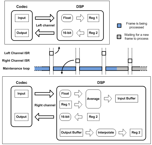
Figure 5.1: Scheduling of the real-time software
5.7.2 Analysis
As mentioned before, the input buffer is a circular buffer. This buffer is made of five sectors with the size of the analysis hop size, which results in a buffer size of 1280 samples. The writing pointer is incremented each time a sample is written and wraps around at index 1279. When four sectors are full, all samples of this frame are copied to a linear array which is the current frame to be processed. Before being copied, each sample is multiplied by its corresponding window coefficient in order to perform windowing as described in equation 3.1. The linear array is designed to receive complex numbers. Each even index (0, 2, … , 1022) represents the real part and each odd index (1, 3, … , 1023) represents the imaginary part. Since the initial signal is real, all imaginary elements are set to zero. The Fast Fourier Transform is then computed from the current frame values. The routine from Texas Instrument is used for this purpose. The latter is very efficient as it makes use of the specific architecture of the DSP to speed up computations (e.g. bit-reverse order indexing). The overall process is shown in figure 5.2.
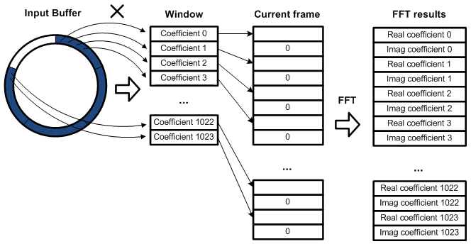
Figure 5.2: Implementation of the analysis stage
5.7.3 Processing
Once the FFT is performed, the processing is performed. Equations 3.2, 3.3, 3.4, 3.5, 3.6 and 3.7 are computed for each value of k, where k goes from 0 to 1023 since there are 1024 samples per frame. The overall number of computations (in floating-point) for each frame is summarized in figure 5.3. A floor operation is similar to a rounding operation except that the fractional part is always discarded.
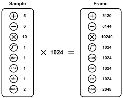
Figure 5.3: Number of operations per frame
5.7.4 Synthesis
After processing, the frame is converted back to the time domain with an Inverse Fast Fourier Transform. Once again, the routine from Texas Instrument is used. The imaginary part should normally go to zero after this operation. However, rounding errors will cause the imaginary to be small but nonzero. The imaginary part is simply discarded since only the real part is windowed and overlap-added at a specific location in the output buffer. These operations are identical to those in equations 3.8 and 3.9. The output circular buffer is made of seven sectors that have the length of the synthesis hop size. This number of sectors is required in order to avoid data corruption. The memory allocated must be sufficient to accommodate for the largest synthesis hop size. In this case, the algorithm is limited to four semitones down and up. The largest synthesis hop size is shown in equation 5.2.

Equation 5.2: Maximum synthesis hop size for a maximum of four semitones up
This implies that the output buffer size must be at least 2261 samples (7x323). This is rounded up to 2300. The index wraps around at the output frame size minus one. The overall process is shown in figure 5.4 for a synthesis hop size of 203 samples. The dashed zone in the buffer represents data that are reset to zero.
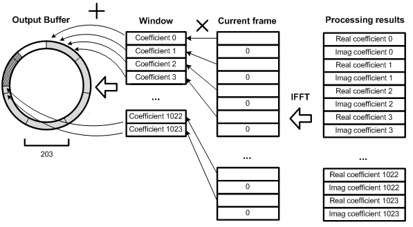
Figure 5.4: Implementation of the synthesis stage
It is necessary to reset data to zero at some point because this is an overlap-add operation. Since the buffer is circular, the sum needs to be reset otherwise past data would corrupt the new data.
5.7.5 Resampling
As explained before, resampling is used to achieve pitch shifting after time scaling. In this case, a reading pointer jumps at different places on the output buffer in order to retrieve output samples. Most of the time, the sample index desired is not an integer number. This is due to the fact that the reading pointer is incremented by the scaling factor, which is not an integer. When a non-integer index is desired, linear interpolation is used to get the best approximation. For instance, if the desired index is 285.625, an approximation is obtained from the values associated with index 285 and 286. This is shown in figure 5.5.
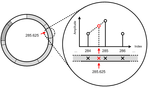
Figure 5.5: Linear interpolation used with the output buffer
Suppose there is a pitch shifting of 4 semitones down, which results in a scaling factor of approximately 0.793. The output frame is made of 812 samples and indexes 0, 0.793, 1.586, … , 811.207 are read. Exactly 1024 samples are thus retrieved when the reading pointer jumps over the complete output frame. The number of inputs is therefore the same as the number of outputs, which results in pitch shifting.
|
Previous: Hardware |
Next: Performances |
Copyright © 2009- François Grondin. All Rights Reserved.